 Imagine
that the original system is modified by adding a water source which flows into
the tank at a constant rate. If we consider dh/dt, we now
have two factors influencing it:
Imagine
that the original system is modified by adding a water source which flows into
the tank at a constant rate. If we consider dh/dt, we now
have two factors influencing it:Torricelli's Law and Fluid
Dynamics
MATH 2413 Research Project 2002
Home | Representation | Analysis | Experimentation | Comparison | Extension | Presentation
Extension
Pick an extension problem:
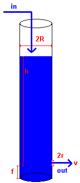
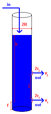
System A: One-Hole System with Inflow
Imagine
that the original system is modified by adding a water source which flows into
the tank at a constant rate. If we consider dh/dt, we now
have two factors influencing it:
-->Water leaving through hole (variable rate)
-->Water entering through top (constant rate)
If these two rates are ever equal, equilibrium will be reached. We seek to find that equilibrium. For simplicity, only Pipe BS will be used.
Experiment 3: Calculating the Equilibrium Point of System A
Procedure: Keep the pipe unplugged and fill it with water coming from
a constant source of water (for example, a showerhead).
After about four minutes, plug the hole.
Measure the time it takes for the equilibrium water column to drain. Use this
to find the height of the water column.
Data:
| Trial 1 | Trial 2 | Trial 3 | Trial 4 | Trial 5 | Average |
| 42.9 s | 39.1 s | 43.5 s | 43.7 s | 44.1 s | 42.66 s |
We can convert this to the equilibrium height of the water column by solving
the BS height equation for a new h0, given the value for
t. This can be done because dh/dt is dependent only
on the height, not the time; in other words, it is essentially homogeneous.
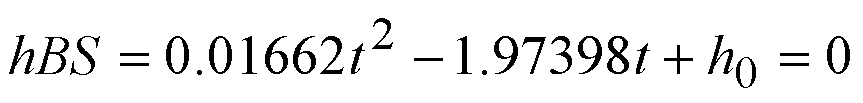
If t = 42.66 s, then the equilibrium height is 53.96 inches.
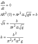
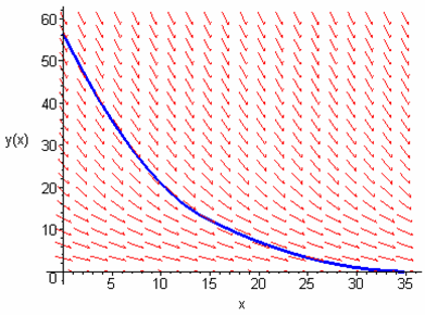
We can solve for this height theoretically by creating a differential equation and setting dh/dt = 0.
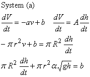
This is not solving by typical ODE methods, but slope fields and numerical
methods can be used to analyze the equation:
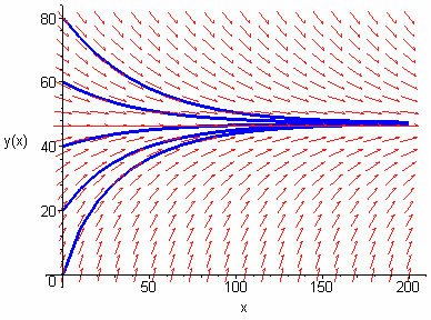
Note that there seems to be an equilibrium water column height near h = 48 inches. (Note that in the slope field y stands for h and x stands for t.)
b, the rate of inflow, was found by finding the time it took to fill
a bucket with known radius r and height h by the water source.
We used a bucket with a cylindrical shape:
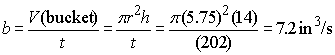
With this information, h was calculated to be 47.8 inches. Our experimental
height was approximately 6 inches too high, with a percent error of 12.9%. Some
possible sources of error include the uncertain value used for alpha, as well
as any experimental errors involved. Furthermore, the theoretical height equation
was used to convert the draining time to a height, not the actual equation,
and that could have greatly impacted the results.
System B: Two-Hole System with No Inflow
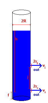 The
system here acts in a piecewise fashion. When the water column height is above
the second hole, water is draining out of both holes. When the water column
height is below the second hole, the system acts identically to the original
system.
The
system here acts in a piecewise fashion. When the water column height is above
the second hole, water is draining out of both holes. When the water column
height is below the second hole, the system acts identically to the original
system.
Its differential equation for when the water column height is above the second
hole:
The slope field of the piecewise function created by this ODE is below:
Note the slight shift in curvature near where the transition takes place. For
the pipe used, this was at h = 14 inches. The numerical solution to
the draining time for this system is 35 seconds, as shown by the slope field
above.
The draining time was also calculated experimentally, with the following results:
Trial 1 - 41.6 s
Trial 2 - 30.9 s
Trial 3 - 31.2 s
Trial 4 - 40.9 s
Trial 5 - 41.0 s
Average - 41.1 s
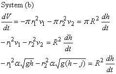
System C: Two-Hole System with Inflow
 This
system is a combination of Systems A and B, with the following differential
equation and slope field:
This
system is a combination of Systems A and B, with the following differential
equation and slope field:
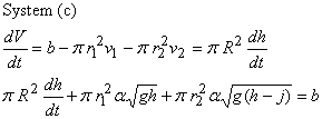
By setting dh/dt equal to 0 in the differential equation above, we find that the suggested equilibrium height will be 19.8 inches. This system was observed qualitatively with a pipe with 4 holes spaced out in 14-inch increments. The first two holes had water flow while the rest did not, meaning that the equilibrium height was in fact between 14 and 28 inches, as predicted by theory.
Extension A: Two-Tank System with No Inflow
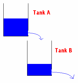 Suppose
that two tanks are arranged such that Tank A empties via gravity into Tank B,
through which water can also leave. The tanks and holes are identical, and there
is no inflow. When Tanks A and B were modeled after Pipe BS, the following information
was gathered:
Suppose
that two tanks are arranged such that Tank A empties via gravity into Tank B,
through which water can also leave. The tanks and holes are identical, and there
is no inflow. When Tanks A and B were modeled after Pipe BS, the following information
was gathered:
Tank A:
![]()
Tank B:
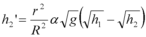
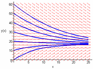
Extension B: Two-Tank System with Inflow
Suppose that water entered Tank A at the constant rate b, same as before. The following changes would then occur to the system:
Tank A: ![]()
Tank B: ![]()
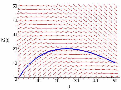
Phase Diagram:
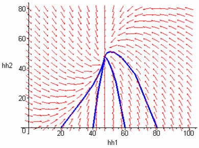
Note that the horizontal axis is Tank A and the vertical axis is Tank B. An equilibrium is reached near the point where the height of both tanks' water column is 48 inches.
Extension C: Calculus of Variations
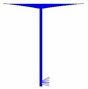 Consider
the problem of finding the shape of the water tank that minimizes the time it
takes to drain a given volume of water. There are two potential scenarios, one
involving a normal smooth curve, and one involving a degenerate case such as
the one shown on the left. In this diagram, the water column is height is so
high that water drains very quickly, yet the pooling of the water at the top
minimizes the change in the height until later in the system. While this may
work to drain most of the water, the drain time for the column itself
could still potentially be long.
Consider
the problem of finding the shape of the water tank that minimizes the time it
takes to drain a given volume of water. There are two potential scenarios, one
involving a normal smooth curve, and one involving a degenerate case such as
the one shown on the left. In this diagram, the water column is height is so
high that water drains very quickly, yet the pooling of the water at the top
minimizes the change in the height until later in the system. While this may
work to drain most of the water, the drain time for the column itself
could still potentially be long.
Not enough resources and knowledge were available for the researchers to fully consider and solve this problem as of this time.
![]()
![]()